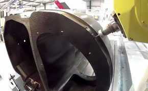
Delcam will be showing its latest developments for the machining and inspection of composites at the JEC exhibition to be held in Paris from 10th to 12th March, 2105. These will include the latest releases of its PowerMILL machining software for high-speed and five-axis machining, including the PowerMILL Robot version for the programming of robots, and of the PowerINSPECT inspection software, plus a range of adaptive machining solutions to allow more accurate manufacture of composite components.
PowerMILL is used by many composites manufacturers for the production of master models, moulds, jigs and fixtures, as well as for the trimming and drilling of components, both with machine tools and with robots. The latest release offers a more complete solution for complex machining operations, including complete control of the position and orientation of the machine head during five-axis machining. The program also includes a range of enhancements to existing functionality to enable both faster programming and faster machining, in particular with the Vortex high-efficiency area-clearance strategy.
 The latest release of PowerINSPECT has a new interface with new icons that make the software more intuitive and even easier to use. Other enhancements in the new version include the ability to create compound items, and so speed up and simplify repetitive measurements, enhancements to the measurement dialogs and a further increase in the range of geometric features that can be inspected.
Delcam will also demonstrate new ways in which machining and inspection can be integrated to give adaptive machining. One example of this integration is electronic fixturing. With this technique, toolpaths are adjusted to match the actual position of the surface of the workpiece, rather than trying to align the part into exactly the nominal position specified in the CAM system. It can overcome the problems caused when machining large, flexible composite panels.
The first stage in this approach is to create a probing sequence in the inspection software, preferably using off-line programming so there is no interruption to the machine tool’s cutting time. This sequence is used to collect a series of points from the workpiece, which can be used map the surface of the part. Any mismatch can then be calculated between the nominal position used in the CAM system to generate the toolpaths and the actual position of the workpiece surface in relation to the machine-tool bed. A modified set of toolpaths can then be created within the CAM system. This approach can ensure that any pockets cut into the surface of a composite part will be in the correct positions. Similarly, by using a map of the actual surface, the user can ensure that any holes and counter-bores are drilled to the correct depth, relative to that surface.


