New MEP process takes hole deburring to new depths
Burr formation creates challenges for part manufacturers across all industry segments, especially when drilling deep through-holes in critical components. In these applications, burrs of excess material form at both the entrance and exit of the workpiece, with the exit burr posing the most challenge. These burrs can lead to poor part quality and production inconsistencies, which are unacceptable in aerospace and other closely regulated industries.
Manufacturers traditionally remove burrs with hand grinders, emery cloth or other manual processes. These methods, however, are slow and require the part to be moved and refixured for the deburring process. Even when performed by skilled personnel, it is impossible to achieve part-to-part consistency in manual deburring operations.
Mechanised Edge Profiling (MEP), on the other hand, employs an engineered tool, guided by a machine tool’s CAM program, to remove burrs quickly and consistently. Hole edges can be finished to high-tolerance specifications on the same machine that drilled the hole initially.
Furthermore, Seco has developed a new MEP process that keeps exit burrs from negatively impacting tool rigidity, machining accuracy and tool life in deep, small-diameter through-holes.
The method combines innovative tool design with 5-axis toolpaths to enable fast, repeatable deburring of holes deeper than 10 times diameter.
End user demands
The aerospace industry specifies dimensions for certain part and hole edge conditions, including chamfer and radii. These features typically undergo approval and certification processes to meet tolerances measured in hundredths of a millimeter as well as ensure consistency from part to part. The deburring process has to achieve a precise balance between machining away the burr without removing material from the part.
Standard deburring and profiling tools used for MEP processing of part edges and other features include solid-carbide chamfering end mills as well as tools that employ indexing inserts with complex cutting geometries. Custom MEP tools have specific radii, chamfers, angles and combinations of those cutting edge features. The most sophisticated deburring tools have edge designs that produce a chamfer with a radiused edge preceded by lead-in and lead-out angles designed to prevent formation of secondary burrs.
MEP tools commonly have square cutting edges, but ball nose and lollipop-style tools are available for profiling edges on contoured components that would otherwise restrict access of square-edged tools. Applied on a 5-axis machine, a ball nose tool can scan the line of a complex part profile and create a radius on a long contoured edge.
Toolmakers also provide tools custom-engineered to profile edges and remove burrs at the entry or exit of larger through-holes. The custom tools feature complex cutting geometries. When cutting conditions are stable and cuts are smooth and uninterrupted, the tools permit use of more aggressive cutting parameters. Conversely, when features such as access holes interrupt the cutting path, parameters are more conservative to minimise tool wear and failure.
Deep, small-diameter holes
The exit ends of deep, small through-holes are challenging to deburr because they require small-diameter tools. As hole depth grows, the tool’s length-to-diameter ratio also increases, making it less resistant to cutting forces and more prone to vibration, chipping or breakage. Moderation of the cutting parameters is necessary and deburring may not be fully effective.
Tool and process development
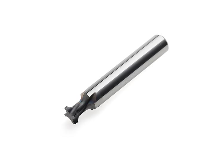
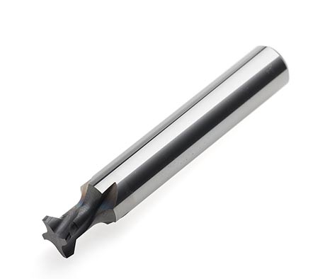
Seco has developed an innovative tool concept and combined it with 5-axis toolpath strategies that facilitate effective deburring of the exit area of deep, small-diameter through-holes.
The tool features a tapered shank with a large neck diameter where the tool enters the part. The design provides a 0.05-mm clearance between the neck and diameter of the hole. Below the entry of the hole the tool tapers to a smaller diameter and at its end are cutting edges.
The CAM toolpaths employ 5-axis motion to tilt and rotate the workpiece so that the centerline of the tool circles around a point and describes a conical form at the hole exit, where the tool’s cutting edges remove the burr. At the same time, the neck of the tool at the hole entry effectively remains stationary and does not interfere with the sides of the hole. A Z-axis movement positions the tool in the hole and then the machine’s 5-axis capability combines X, Y, and Z motion to perform the deburring process.
Application and testing
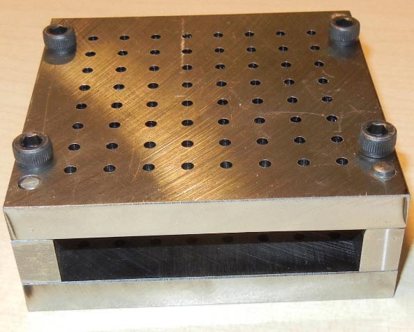
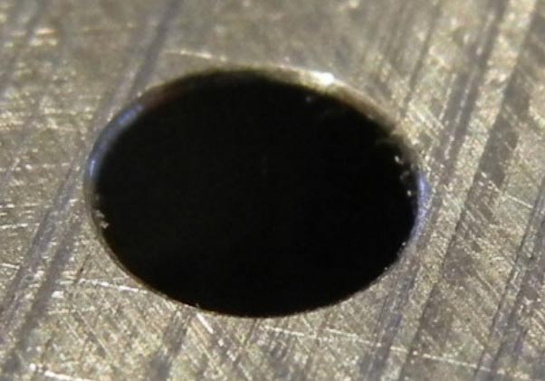
Seco initially tested the tools and toolpaths deburring the exit of a 3.2-mm diameter, 36-mm deep through-hole. The length-to-diameter ratio was greater than 10:1. Initial trial-and-error testing arrived at an optimal rotation rate of 1,200 rpm, a speed that enabled the tool to complete 128 holes without replacement.
Deburring each hole required no more than three seconds, compared to manual deburring techniques that could require a full day or more to deburr an equivalent number of holes. Because the CAM program and machine control handled the tool’s movement, the deburring results matched exactly from the first hole to the very last.
Programming details
To programme tool movement before the MEP process, the machine operator must enter the exact location and definition of the surfaces to be deburred. The tool length must be defined as well. Tools are ground to a tolerance within 0.0375 mm. The front end of the tool is ground in the same operation as the cutting edges, producing a relationship between the tip of the tool and the cutting edge within 0.0125 mm. The tool length is specified in the CAM program; the operator can confirm the tool length off the machine with a presetter or on the machine via a laser or touch probe.
Conclusion
Manufacturers continually respond to customer demands for increasingly tight part tolerances. The aerospace industry leads the trend, but requirements for precision and consistency are becoming stricter in the medical, energy and other industries as well.
Deburring, an essential element of precision part production, has long been carried out through manual methods. Unfortunately, these operations can be inconsistent from part to part and are expensive in terms of labor, setup and part handling expense. In fact, some end-users have banned manual deburring because it cannot be documented and certified.
Mechanised Edge Profiling (MEP) provides a method to deburr components and profile part edges that are consistent, documentable and cost efficient. Seco’s most recent development in MEP combines custom tool design with innovative 5-axis programming to facilitate consistent and productive deburring of the exit area of deep, small-diameter through-holes.
Sidebar
MEP for multitasking?
Some MEP tooling combines the machining of a part feature with a deburring operation. Select end mills, for example, locate the MEP machining feature at the top of its cutting zone to machine the hole diameter and then deburr the entry point in the same operation. Keep in mind, however, MEP deburring tools for both the entry and exit of deep, small-diameter through-holes face special considerations.
Analyses of MEP applications have indicated that tools engineered to remove burrs at the entry of a through-hole provide longer tool life than those designed for eliminating burrs at the exit end. Tools for deep-hole exit burrs have a higher length-to-diameter ratio, making them more prone to instability and vibration that, in turn, accelerate wear.
Therefore, a tool engineered to deburr both the entry and exit of a deep through-hole would exhibit longer life for the entry feature than for the exit feature, resulting in the need to discard the tool with much of its capability unused.
Additionally, MEP tools that deburr the entry area of a hole can be reground, but the critical relationship between the cutting edge and tool tip in MEP tools for deep, small-diameter through-hole deburring precludes regrinding. The reason is that applying a reground tool would involve changing the offset in the machining program, something prohibited by the strict protocols of aerospace machining practices.
By: Teun van Asten MSc., Engineer Marketing Services Solid Milling, Seco Tools