Delcam has released the 2016 version of its PowerINSPECT inspection software, the world’s leading hardware-independent 3D inspection solution. The new release includes greatly enhanced options for section measurement, more comprehensive collision avoidance, improved point cloud inspection, the ability to add notes to reports, and improved user control of CNC surface inspection routines.
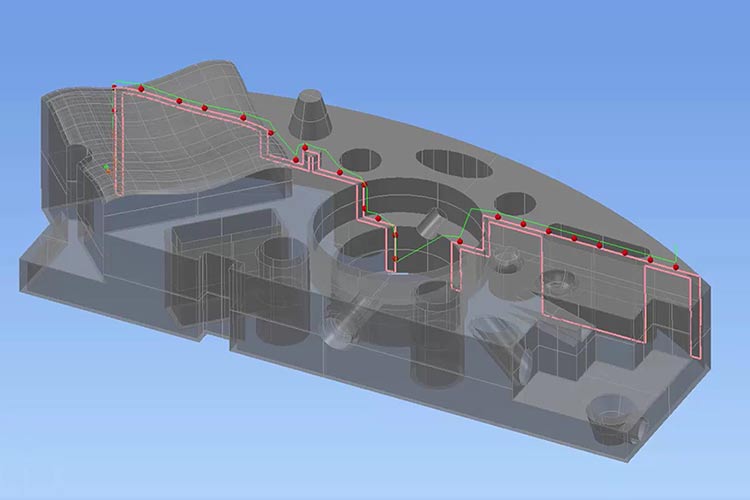
Section inspection has been improved with easier creation of sections, better visualisation and enhanced reporting. The enhanced options for section editing in PowerINSPECT 2016 include a slider that can be used to move the section through the part with real-time updating of the CAD view. A specific value for the section intersection can still be entered if required.
New graphics options help with visualisation and reporting. In the CAD view, the default option highlights the section cut and displays a semi-transparent representation of the material in the foreground, providing an accurate 3D visualisation of the section in place on the part. During section creation the shading is updated dynamically as the section moves through the model. Alternatively, the near side can be hidden completely, or the complete CAD model can be shown in a solid colour as before.
Once the desired section has been chosen, the inspection path can be generated automatically. The points generated can be edited if necessary. The section can also be viewed and reported as a 2D true view of the section profile that is currently selected.
As with other PowerINSPECT measurements, the results of the section inspection can be viewed as spot confetti, deviation lines or vector lines. The results can be displayed either on their own or as part of a larger inspection sequence.
Automatic collision detection was introduced in PowerINSPECT 2015, with probe paths adjusted automatically when a direct move between inspection features would result in a collision. A new collision-free mode extends this capability by automatically creating links between inspection features as necessary. If a potential collision is detected, the software automatically creates and calculates a new linking path that avoids the obstacle. Collision avoidance is recalculated when the order of the inspection sequences is adjusted in the sequence tree.
Intermediate paths can still be created or updated manually. This is required when the CAD model does not include complete information about the physical reality, for example if clamps or fixtures used to hold the part are not included in the CAD data.
PowerINSPECT 2016 has improved reporting with the ability to include additional user-defined information. New ‘Report Note’ items allow the user to insert additional observations, including text and pictures. As with all other items in the report, the notes can be shown, hidden and re-ordered within the report.
The formatting of labels has also been enhanced, particularly for GD&T items. New options have been added to the dialog for session settings to enable further control of the label display. Furthermore, the label sizes can be edited in the session settings and grid lines can be displayed for clearer reporting.
A number of enhancements have been added for inspections based on point clouds. Firstly, point clouds can be imported from DMT and STL triangle files. Scanning acquisition performance is improved and points can be saved from a point-cloud scan each time there is a pause during the scan. Several point-cloud items can also now be created in a single point-cloud session without having to leave the full-screen acquisition view.
CNC surface inspection has been improved, making it easier to produce consistent results across a batch of components. New surface inspection groups provide better user control of point naming, and the positioning, contents and formatting of report images. It is also possible to reference CNC surface inspection groups directly in RPS alignments.
Finally, there are significant usability improvements for the CAD File Manager. It is now possible to import one or more CAD files by dragging and dropping them into the main graphics window. The highlighting and visualisation of individual objects in CAD models is further improved, making it easier to identify named objects and levels.


