Bridging the Gap: TaeguTec Solutions for Knuckle Gap Milling
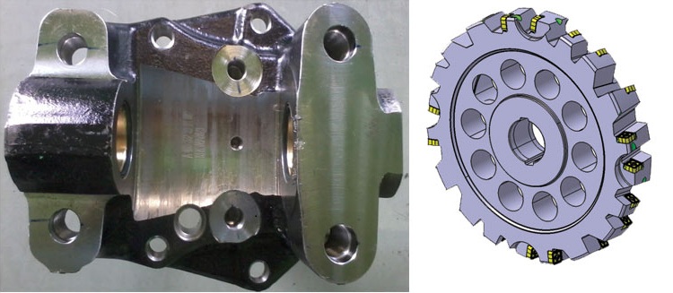
In automotive suspension, a steering knuckle (or spindle knuckle or axle arm or stub axle) is that part which contains the wheel hub or spindle, and attaches to the suspension components. Materials used for knuckle parts are basically Cast & SG Iron and Alloy Steels. Depending upon the type of vehicle, the material is chosen. We can widely see Forged Steel as a material in Heavy vehicle (Trucks & Buses) and SG iron in passenger cars.
The major amount of material removal in knuckle is done by face milling, drilling & gap milling.
Face milling and drilling can be addressed with standard products. Application like gap milling really calls for an engineered solution according to the knuckle design.
GAP MILLING – ROUGHING
Material: Forged Steel (Common in Heavy vehicles – Trucks & Buses)
Approach 1 : Special purpose machines (SPMs) with good power availability ( i.e : 11 kW and above ).
SPM approach is more suitable for transfer lines where only one particular operation is performed. This can be used for rough machining of Gap where the stock levels will vary from 2 – 8 mm. This option is capable of running at low to moderate cutting conditions.
Example 1: The cutting speed can be from 80 ~ 120 m/min and table feeds can be from 60 ~ 100 mm/min. Here we can use the options of inserts with cutting edges on both sides.
Example 2: Square insert with 8 cutting edges with specific corner radius requirement. In this combination we can look at using corner radii up to 3.2 mm. When the corner radii requirement is more than 3.2 mm, having more number of cutting edges becomes a limitation due to increase in the insert size which will result in less number of teeth and higher cutting resistance. Here we go for single sided inserts which can be triangular shape or square shape with 3 and 4 cutting edges respectively.
Case Study
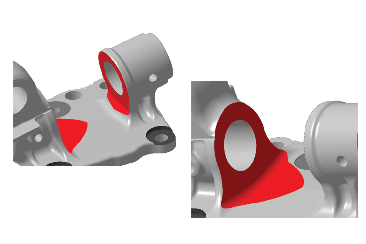
Application: Rough machining of Knuckle Gap:
Knuckle gap : 112 + /-0.25 mm
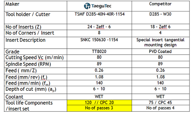
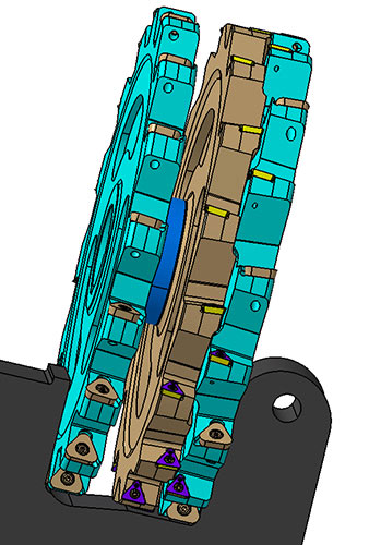
Cutter used: Dia 250 mm Right Hand & Left Hand for the front and rear sides. And D 250- 14 mm thick + Dia 250; 59.5 mm thick cutters for inside milling.
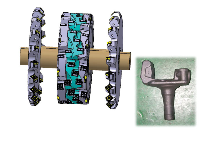
In the above combination, we used double sided square inserts in all the cutters. The outer cutters have inserts with chamfer and inside, GAP machining cutters have R3 corner radius. This combination can give a tool life of 200 ~ 250 components per edge set at a cutting condition of 80 ~ 100 m/min and a feed of 60 – 120 mm/min.
We should keep in mind that the work piece clamping rigidity plays a vital role in this set up. The clamping of the work piece must be good along with machine capability because we are not only machining the GAPS, also the front & rear sides.
Approach 2: Machining Center route
This approach is more suitable for controlled depth of cuts. The depth cuts cannot cross 3~4 mm. When the DOC is higher we go for more number of passes. This particular approach is good for the recent market trend where there is high demand for model change. The machine can accommodate the model change by changing the fixture locating plates and clamps.
There will be the limitation of cutter diameters and tool holding capacity of the machine. The radius formation inside the gap will be by interpolation of the cutter. Here we are forming the radius of R158 by using a Dia. 240 cutter. This kind of solution can be used at cutting speeds between 100 ~ 180 m/min and feed rate of 200 – 400 mm/min with controlled depth of cuts.
We have to be very cautious on the tool length in this case. If the tool length is longer due to the knuckle design or the clamping mechanism, we need to optimize the cutting condition.
Approach 3 (In case of clamping rigidity and machine power being a limitation)
Case Study:
Rough gap Milling: Knuckle
Material: Forged Steel
Machine: SPM – Special adaptation/ Flange Type Mounting.
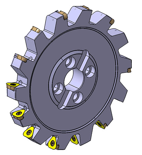
Cutters used: Dia 350 mm Right hand & Left Hand with corner radius 5 mm.
Here we can clearly see that we have used triangular inserts with 3 cutting edges where the cutting forces will comparatively lower than the double sided inserts. The corner radius requirement on the component is R5 and the cutter diameters are also bigger.
Here we use similar cutting condition and achieve good tool life!
GAP MILLING – FINISHING
When it comes to finishing of the knuckle GAP, irrespective of SPM approach or Machining Center approach, there is a wide range of insert choices.

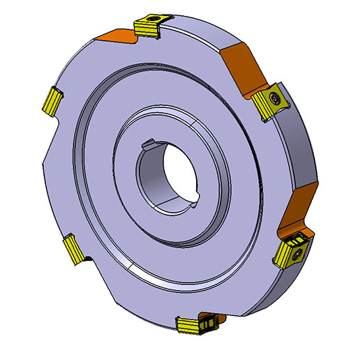
a) Tangential mounting of inserts on the cutter (refer the below picture). You can see the cutter is chopped from both sides in order to accommodate on the machine ATC.
This kind of tangential mounting gives good surface finish values between Ra 1.6 ~ 2.3 and the flatness on the walls lesser than 0.05 mm . We can use cutting condition Vc 150-200 m/min and feed 0.07~0.15.
It is always better to keep stock levels for finish as 0.7~1.2 mm considering the corner radii of the inserts.
b) Radial mounting type with triangular inserts:
The below design is for SPM machine where 2 different cutters are mounted on the arbor with a spacer and used for finishing of the GAP. For machining center, there can be a single cutter with inserts on both sides.
We can machine the component by Z axis movement or by B–axis rotation.
Lug Machining in SG Iron (usually smaller knuckles common in passenger cars and light vehicles.)
Machining of Grey-Nodular iron knuckle are simpler compared to the steel ones because :
- Machinability is easy. Machining areas are smaller comparatively
- Chip evacuation is not at all a concern
- Size of the knuckles are also smaller – Clamping of the part is simpler
- Dry cutting can be performed in order to achieve higher life and avoid coolant usage.
- Moderate machine rigidity is good enough. BT40 / ISO40 machine also can be used.
Cutter designs that can be looked at:

Case Study:
Limitation: BT40 machine with 7 kw / Stock removal:2~3 mm .
Customer demand: Low cost / piece

Especially these kind of smaller knuckles are machined in MCT only. The cutting speeds can be from Vc 200 ~300 m/min, and feed can be 0.1 ~ 0.2 mm/ z.